Add A Servo Motor
To Your Lane Changer
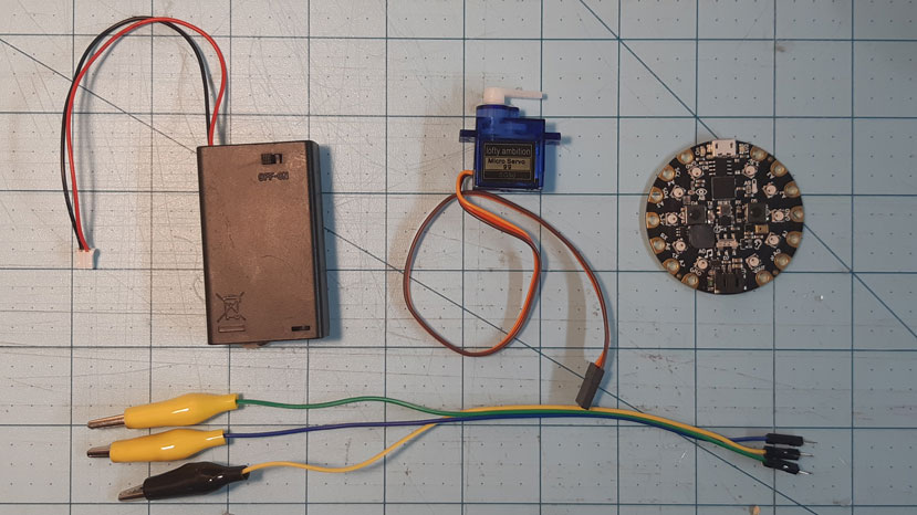
What You’ll Need
- Servo Powered Lane Changer Design Template
- Cardboard (corrugated)
- Glue Gun and Glue Sticks
- Box Cutter or Sharp Scissors (and an Adult’s Help)
This project is for those of you who are looking to add electronics to their Marble Run, and may in fact already have a Circuit Playground at their disposal. This may be a bit more of advanced project for those interested
STEP 1
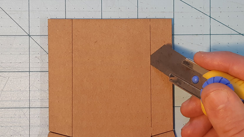
The Frame
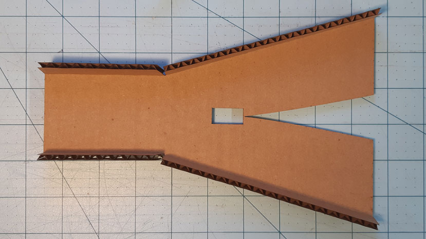
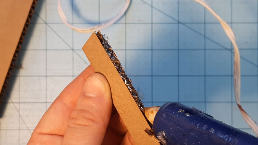
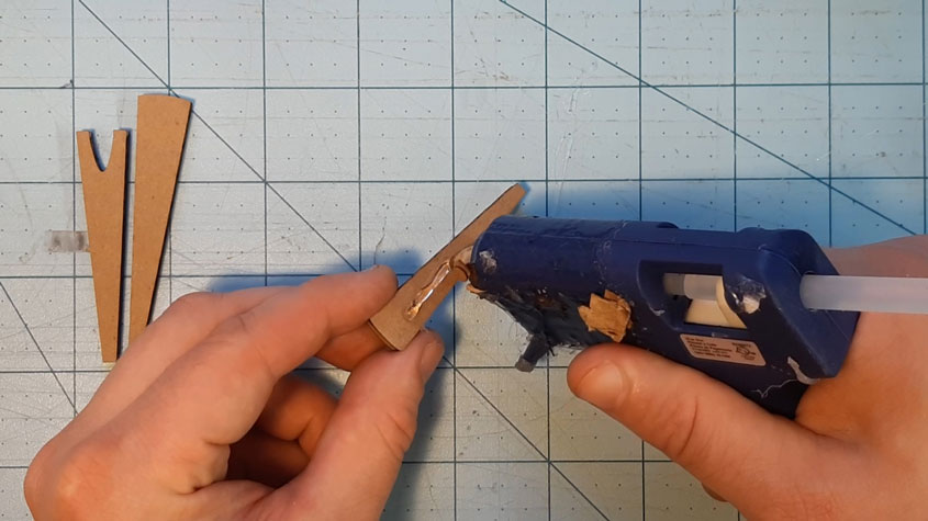
As with all of the other projects, you can begin by printing and cutting out your design templates, gluing them to cardboard, and then cutting those pieces out. From there, you can start by lightly cutting along the dotted lines, careful not to cut all the way through. This will allow you to bend the frame downward and glue it into place
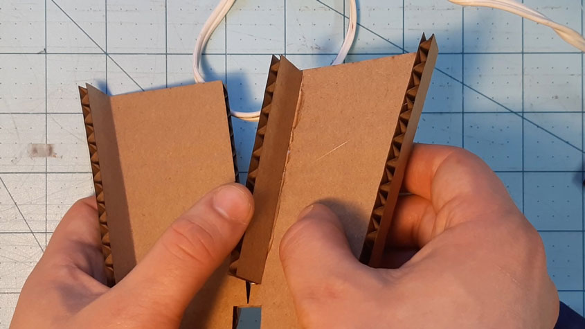
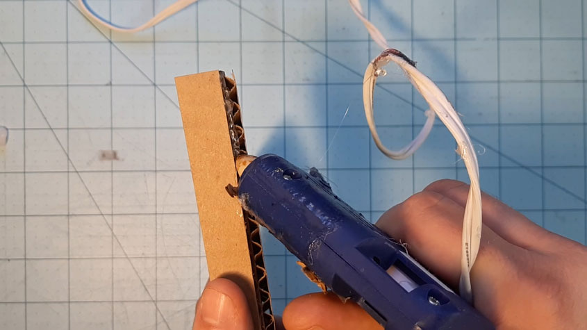
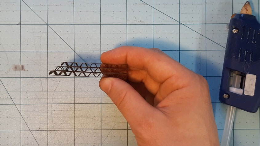
Take the pieces labelled Walls and glue those next to the V-shape, as close to the edge as you can
STEP 2
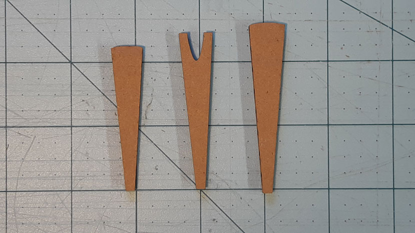
The Flipper
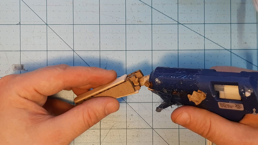
The next step requires you to take all three Flipper pieces (top, middle, and bottom). Beging with the bottom piece and glue the middle piece on top of that, making sure the pointed ends are lined up (the middle should stick out a little further on the other end). Once that is dry, add some glue to the top of the middle piece and attach the top piece to that. They should looks sloped as in the final picture here

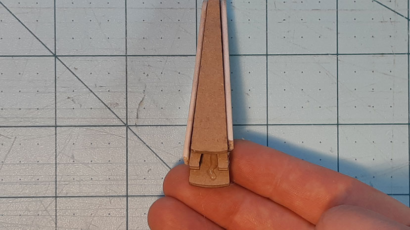
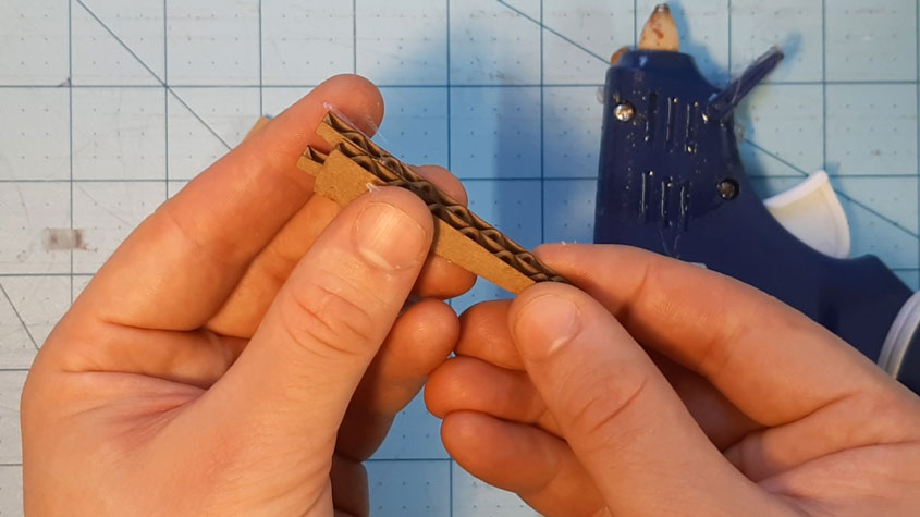
When that has dried, cut a popsicle stick in half, and glue it to either slide of the Flipper.
STEP 3
Putting it Together
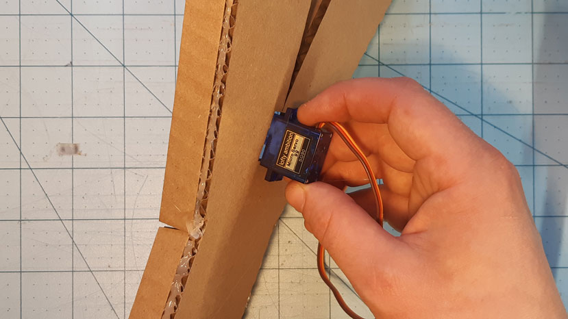
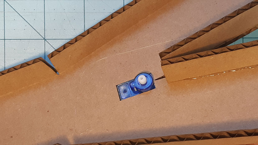
The final step before coding requires you to take your 180 degree servo, and stick in through the hole so the white arm comes through the top. Make sure the circle nub on this servo is near the back of the hole. The servo should fit snugly, but you can always add a bit more glue on the bottom to secure it in place
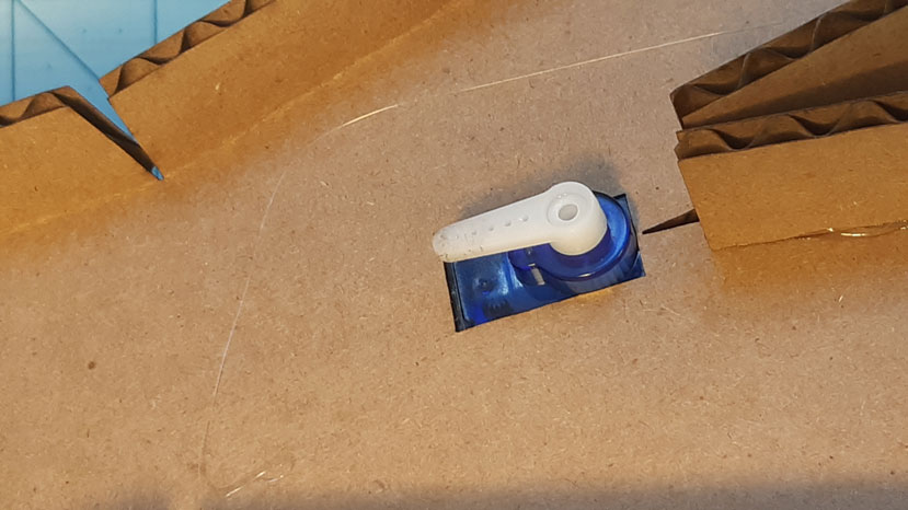
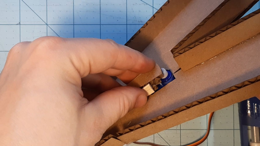
Position your tiny- white-arm onto the gears of the servo, and glue your flipper to this arm, being very careful to not get glue inside the motor
STEP 4
Hooking Up The Tech
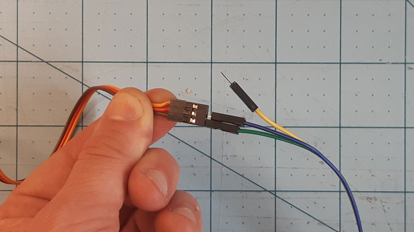
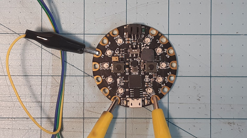
Now you will need to connect your Servo Motor to your Circuit Playground so you can code your CPX to ‘talk’ to your gate. First we need to attach the wire clips to the 3-wired adapter exiting the motor. The BROWN wire is the GROUND, the RED wire is the POSITIVE, and the ORANGE wire carries the SIGNAL. We need to connect these clips to the little copper rings on the outside of the Circuit Playground. The BROWN wire will connect to one that says GND (the ground), the RED to a circle that says 3.3V (the positive power), and the ORANGE to A1 (where we program the signal to connect)
STEP 5
Coding With MakeCode
MakeCode is a easy to learn block-based coding platform which is surprisingly intuitive to learn. It is a web-based coding platform, so you can access it and all your saved projects from anywhere; just visit https://makecode.adafruit.com/ to get started.
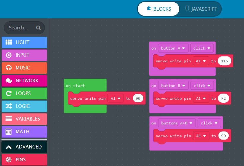
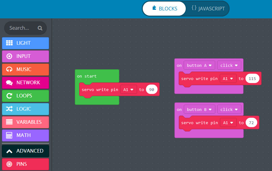
On the left I have included a photo of what your completed code may look like, but getting there is the fun part.
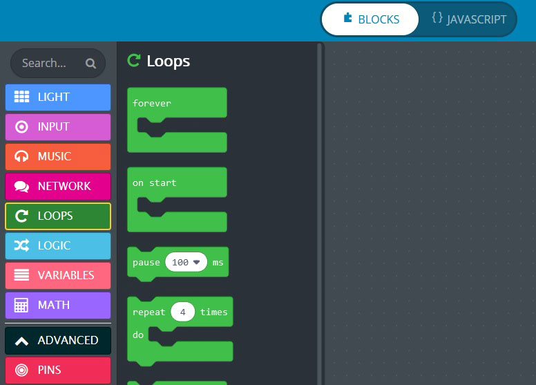
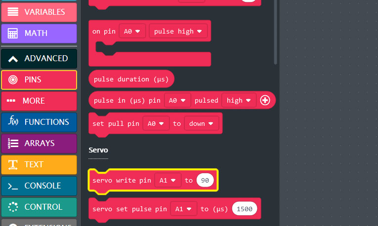
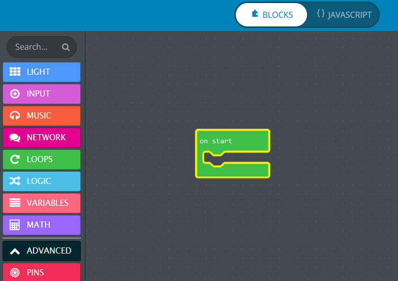
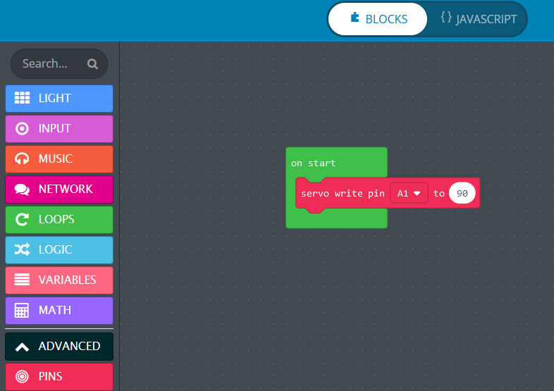
We will start by setting our servo to return to the middle every time we power it on (just so we’re sure it’s working). We need to do this by opening up the Loops drawer, and dragging the On Start command into our window. See how it looks like a mouth? well all the code we put in that mouth, will run when we start CPX. Like I said, we want it to start in the middle, so we need to go back to the drawers on the side and open the one that says Advanced, if we scroll down for a bit, you will find the Pins section, and a command tat starts Servo Write Pin A1… Grab this and drag it into the mouth of your code. See how it connects? that means your code is active. We don’t even need to adjust any numbers because the 90 that’s there means your servo is in the middle
Buttons
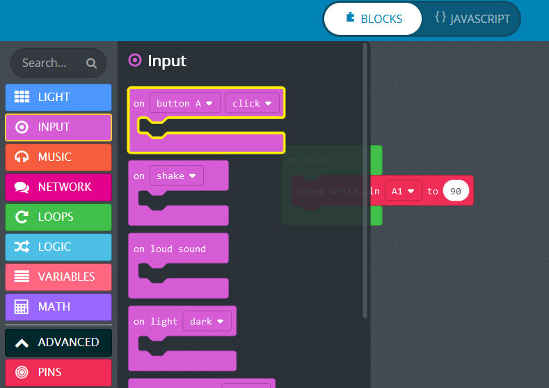
Great! Now we want to move our Flipper by pressing a button. On a CPX, a button is known as an Input – a command you put it, to expect a result. So you need to look for the Input drawer on the left, and drag the Button A mouth anywhere onto the screen (it doesnt matter where you place your mouths, they don’t have to be in any specific order to work). Now you want to fill that mouth with a command that will move your servo, so grab the servo write pin command again, but this time, set the number to be a little higher than 90 (above 90 moves the servo to the right, below 90 moves it to the right).
More Buttons!
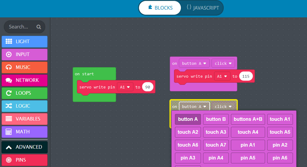
To make the servo go back the other way, we need to access the other button and add another servo write pin command into it. To change what button we’re using, drag a new Button A command from the Inputs panel, but this time, click on the little arrow next to the words Button A. This will bring uop a whole new menu where you can select a different function for your button command. Here we want to select button B, and use the servo write pin command in it to have a number lower than 90
STEP 6
Download, Power On, and Have Fun
All you have to do now is save your code to the Circuit playground. Attach your CPX to your computer with a USB cable, and then hit the DOWNLOAD button in the lower left hand side of the screen and follow the instructions. After the lights flash and the download is complete, disconnect it from your computer and hook the battery pack to the appropriate connector. Your Servo Powered Lane Changer is now controlled by code that your wrote! Congratulations!